
Connecting a Spindle with an SSR or VFD
Control a spindle through a Solid State Relay for simple ON/OFF operation or through a VFD for variable-speed control.
Spindle Control Options
The Rabbit Board 4-Axis provides a low-voltage 5V PWM spindle control output with a frequency of up to 10kHz, together with a direction control signal. These are control signals only and must never be used to power a spindle directly.
For simple spindle ON/OFF control, the Rabbit Board can control a suitable Solid State Relay (SSR). For variable-speed control, it can provide the speed command to a compatible Variable Frequency Drive (VFD), either directly through PWM or through a PWM-to-0-10V converter.
Electrical Safety Requirements
Spindles, VFDs, and the load side of many SSR installations operate at hazardous voltage and current. Fully disconnect and isolate all power before installation or maintenance, and verify that no residual voltage remains. A VFD may retain dangerous voltage in its internal capacitors after power is removed.
Mains wiring, protective devices, emergency stop circuits, SSR load wiring, and VFD installation must be completed by a licensed electrician. Follow the spindle, SSR, VFD, and converter manufacturer manuals. The Rabbit Board is not a functional safety device and must not be the only means of stopping or isolating the spindle.
Simple ON/OFF Control with an SSR
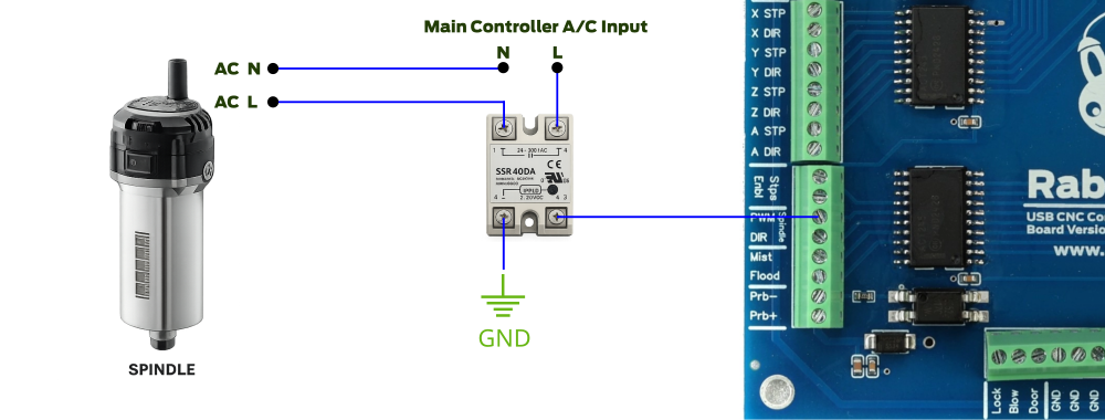
An SSR allows the low-voltage spindle control signal from the Rabbit Board to switch a separate spindle power circuit without placing the spindle load on the controller output. In this configuration, the spindle is either ON or OFF; the SSR does not provide variable-speed control.
Connect only the compatible low-voltage control side of the SSR to the Rabbit Board spindle control output. The SSR load side must be wired into the spindle power circuit according to the SSR and spindle manufacturer diagrams. Never connect mains voltage to a Rabbit Board terminal.
Select the Correct SSR
The SSR input must be compatible with the Rabbit Board control signal, and its load side must match the spindle supply type, voltage, current, and load characteristics. AC-output and DC-output SSRs are not interchangeable. Select an SSR with an adequate safety margin and the required protective components.
Many SSRs require a correctly sized heat sink and suitable ventilation. Confirm the manufacturer's requirements for load type, inrush current, switching method, fusing, enclosure, and thermal management. An incorrectly selected or overheated SSR can fail in the ON state, so the emergency stop system must remove hazardous spindle power independently of the control command.
Variable-Speed Control with a VFD
A VFD controls the speed and operating state of a compatible spindle motor. The Rabbit Board supplies only the command signals; the VFD supplies the motor power. Never connect Rabbit Board signals to the VFD mains input or motor output terminals.
Some VFDs can accept a 5V PWM speed reference directly. Use a direct connection only when the VFD manual explicitly confirms compatible voltage, frequency, signal reference, and isolation requirements. The VFD RUN, ENABLE, FORWARD, or REVERSE terminals vary between models and must be connected through the interface method specified by the VFD manufacturer.
Using a PWM-to-0-10V Converter
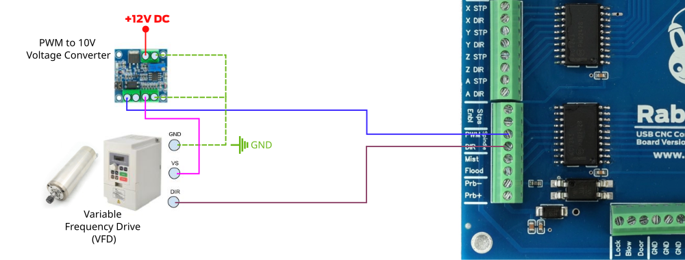
Many VFDs use a 0-10V analog input for speed control. In this case, connect the Rabbit Board PWM control signal to a compatible PWM-to-0-10V converter, then connect the converter analog output to the VFD speed-reference input according to both manufacturer diagrams.
The converter requires the correct supply voltage and signal reference. Its output must be calibrated so minimum and maximum PWM correspond to the intended VFD speed range. Do not assume terminal names such as AI, AVI, ACM, COM, or GND have the same function on every VFD.
Configure Rabbit GRBL Spindle Control
Verify that the active Rabbit GRBL machine profile uses the spindle control type required by the installation. The primary spindle commands are M3 for clockwise start, M4 for counterclockwise start when supported, M5 for stop, and S for the requested spindle speed.
For variable-speed control, review settings such as $30 maximum spindle speed, $31 minimum spindle speed, $33 PWM frequency, and the PWM output range settings $34, $35, and $36. Spin-up and spin-down delays can be configured with $37 and $38. Set these values according to the spindle, VFD, converter, and machine requirements.
Test the Spindle and Reduce Interference
Before the first test, remove cutting tools where practical, secure the machine area, keep the emergency stop accessible, and verify that the spindle can be stopped independently of software. Start at a low commanded speed and confirm the ON/OFF state, direction, speed range, and M5 stop behavior before running a machining job.
Install a suitable EMI/RFI filter at the AC input of the VFD and follow the VFD manufacturer's grounding and shielded motor-cable requirements. Keep VFD input, output, and spindle cables separated from USB, STEP/DIR, limit switch, and probe wiring. If communication becomes unstable only when the spindle starts, stop testing and correct the grounding, shielding, filtering, and cable routing before operating the machine.